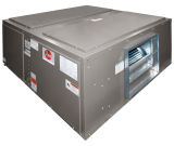
1. Nominal Capacity (Tons)
7.5
2. Stages of Air Flow
VFD - 2-STAGE
CFM Rating
3000 @ .25”
Product Dimensions W X D X H (Inches)
52 X 52 X 27 (horizontal)
3. EER/IEER
11.2/14.8
Metering Device
TXV
4. Voltage
208/230V, 3PH, 60HZ
Configuration
HORIZONTAL/VERTICAL
Supply Opening (Inches)
19-7/8 X 19-7/8
Return Opening (Inches)
47-3/8 X 19-7/8
Single Circuit Stubs Sweat (In.)
1/2 liq. 1-1/8 suc.
Dual Circuit Stubs Sweat (In.)
1/2,1/2 liq. 7/8,7/8 suc.
Motor Type/HP
Belt Drive 2 HP, 3 HP
Motor RPM
1750
Motor # of Speeds
VFD
Blower Wheel
12X12
Belt
A50
Filter Size (std.)
(4) 16 X 25 X 1
Shipping Weight (Lbs.)
396
Item Weight (Lbs.)
330
- CABINET—The pre-painted, sheet-metal cabinet uses 18-gauge material for structural components with an underlying coat of G60 electro deposition powder coating that is tested to withstand a rigorous 500-hour salt spray test, per ASTM B117.
- MOTOR—Inherently protected motors are mounted inside of insulated cabinet to reduce motor noise. A choice of motor horsepower and drive combinations are available to allow you to meet specified CFM at various static pressures up to 2" [.498 kPa] external
- LOW PROFILE—Allows for horizontal installation in most standard drop ceiling applications, and the movement of units through most standard doorways for addition or replacement work.
- FILTERS—One inch [25 mm] throwaway filters are standard, but filter racks are designed to accept either one inch [25 mm] or two inch [51 mm] filters.
- EVAPORATOR COIL—Two circuit, interlaced row split coils are constructed with copper tubes and aluminum fins mechanically bonded to the tubes for maximum heat transfer capabilities. All coil assemblies are leak tested up to 450 PSIG [3100 kPa] internal pre
- VARIABLE FREQUENCY DRIVE—Provides 2-stage airflow for improved part load efficiency. Meets California Title 24 requirements.
- REFRIGERANT CONNECTIONS—Field piping connections are made through a fixed post between two side access panels on either side of the unit. Allows flexibility to meet most field conditions as well as full accessibility after the installation is complete. Un
- DRAIN PAN—The galvanized steel drain pan is designed to trap condensate in either vertical or horizontal installations. Condensate drain connections are located on both sides of the unit allowing complete flexibility to meet most field conditions.
- SERVICE ACCESS—Two removable panels on top and each side of the unit are easily removed for access to motors, blowers, sheaves, and filters.
- HORIZONTAL OR VERTICAL—All models are designed for either application and can be installed in either position as supplied from the factory.

